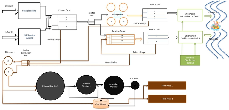
 Click on Pollution Control Facility flow path to watch a video on how treatment plants work
afrench@watertown-ny.gov
Ph: (315) 785-7840
Plant Ops: (315) 785-7841
Fax: (315) 779-2095
Hours
24 Hours / 7 Days
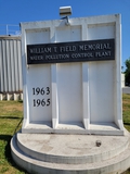
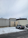
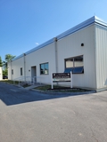 Control BuildingCity of Watertown Pollution Control Facility
The Watertown Pollution Control Facility is designed to treat an average of 16 million gallons a day (MGD) of water. The Facility first went on line as a primary plant in 1966. On December 1st, 1981 the secondary Trickling Filter process went "on line".
The trickling filter process is capable of providing effective secondary treatment for sustained flows up to 8 MGD per day. On August 8th, 1989 a new Activated Sludge process was added to facilitate the Fort Drum expansion.
We currently have two influents and two effluents which discharge into the Black River and can now sustain flows up to 16 MGD. Our discharge permit requires 85% removal of suspended solids and BOD (Biochemical Oxygen Demand).
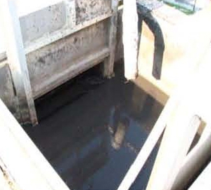
PRELIMINARY TREATMENT
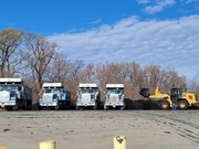
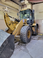 Frontend loader
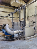 Center-flow screen
Preliminary treatment is preformed to protect the operation of the wastewater treatment plant. This is accomplished by removing from the wastewater any items which can clog or damage pumps or interfere with subsequent treatment processes.
That equipment performing a preliminary function is mainly housed within the Control Building. The screen has approximate ¼ inch openings to intercept all objects in the water larger than the openings (i.e. rags, leaves, “flushable wipes”, baby wipes, twigs.).
The screens travel up to the washer where most of the organic material is cleared from the debris. The material is compressed then removed by the front-end loader and subsequently trucked to a landfill. The next stage of treatment are the detritors, removing grit and larger rubble. Grit is inert material such as sand, egg shells, and pebbles, which are small enough to pass through the screens, yet large enough to have the potential of clogging, damaging, or interfering with subsequent equipment or processes.
 Detritor
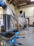 Grit Removal
The Detritors are designed to slow the wastewater to approximately 1 foot per second. This velocity is low enough to allow the grit to settle and fast enough to maintain the organic solids in suspension. There are sweeps in the Detritors which continuously scrape along the bottom of the tanks and collect the grit into adjacent pits. The grit is then pumped to the operation deck and eventually hauled by truck to the landfill. About 25 cubic feet of grit and screenings are removed daily. The wastewater then flows from the Detritors to the raw sewage wet well where it is then pumped by the raw sewage lift pumps to the aerated grit chambers.
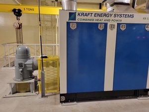
Direct Drive Engine
 Raw Sewage pumps
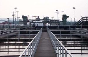
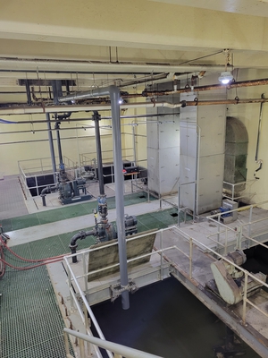
Primary Settling Tank
Water is then pumped by the engines to the aerated grit chambers preceding the Primary Settling Tanks. These chambers replenish the wastewater with dissolved oxygen to prevent septic conditions from developing in the settling tanks or clarifiers. Additionally, the agitation caused by the aeration separates the grease and scum from the organic solids facilitating their removal from the surface. A third function of the aerated grit chambers is to allow additional grit to settle during the approximately 20-minute holding times. The grit is removed from the chambers and is hauled to the landfill (approximately 3 to 4 cubic feet per day).
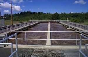
PRIMARY TREATMENT
Primary treatment is designed to remove organic and inorganic solids by the physical process of sedimentation and floatation. The primary settling tanks (clarifiers) measure 250’ x 40’ x 8.2’ and have a hydraulic detention time of about 1.8 hours. Organic and inert settleable solids will settle and are pumped to the gravity thickener as primary sludge at about 0.1% solids by weight. The grease and scum float to the surface and are skimmed off the tank by simple decanting.
The water from the Primary Settling Tanks then flows to the splitter box. This structure receives the flow from the primary settling tank (clarifier) and splits the flow between the Trickling Filter Process (A train) and the Activated Sludge Process (B train). The flow is split 50/50 with the "B" side never receiving more the 8 MGD. The "A" side Trickling Filter Plant can handle the large swing in flows due to the nature of the Trickling Filters.
SECONDARY TREATMENT
The effluent from the primary treatment contains large quantities of colloidal and dissolved solids. For average domestic wastewater, about 60% of the original total solids remain in the water after primary treatment. The secondary treatment process consists of the biological treatment of wastewater by utilizing the many different types of bacteria and microorganisms ("bugs") present in the water. These "bugs" convert colloidal solids into larger settleable solids which can later be removed from the water. This facility presently has two processes for secondary treatment. They are the Trickling Filters process and the Activated Sludge process.
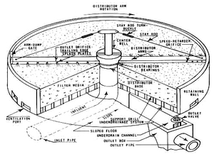
Trickling Filter:
The Trickling Filters at Watertown’s Pollution Control Facility are large circular tanks 5’ deep and filled with stone. The stone is all approximately the same diameter allowing water and air flow through the voids. Wastewater is distributed over the large surface area of filter media (stones) by radial revolving arms. As the water trickles down through the media, the solids within the water come in contact with and cling to the microorganisms attached to the rocks. Once attached, the organic matter begins the stabilization process removing solids from the water. The microorganism colonies are a grayish-green and brown slime. As the microorganisms feed on the solids, they grow and eventually become a "heavy" biomass which sloughs off the rocks and is carried by the wastewater stream.
The trickling filters measure in excess of 120’ in diameter and are covered to maintain a satisfactory environment during the cold winter months. It is in the final clarifier that the "heavy" biomass is removed from the wastewater by the physical process of sedimentation. Each trickling filter is designed to treat between 6 and 8 million gallons of wastewater per day. The pump station located at the center of the trickling filter complex automatically selects the proper hydraulic loading for each filter. The pump station can re-circulate flow back to the head of the filters as needed. Under normal conditions the filters operate in a two-stage series. Additionally, the plant has the capability of alternating lead and lag filters. This practice is called Alternating Double Filtration (ADF), a concept developed in England with the advantage of being able to control slime thickness which tends to reduce clogging problems. Under abnormal conditions of high flow (greater than16 MGD) the filters are operated in parallel mode whereas the flow to the filters is evenly distributed to all four filters then to the final settling tank.
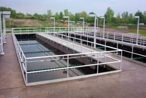
Activated Sludge:
The Primary settling tank flow to the head of the Aeration Tank is mixed with the return sludge from the final settling tank. When the primary effluent and return sludge is then mixed with the activated sludge in the aeration tank, it is called the mixed liquor. To ensure enough mixing to keep the activated sludge in suspension and to maintain sufficient dissolved oxygen, we have air blowers which feed air through a fine air bubbler distribution system located in the bottom of each aeration tank
Mixing and dissolved oxygen is required to sustain the life of certain microorganism. After the wastewater (now referred to as mixed liquor) leaves the aeration tanks it enters the final settling tanks (clarifiers). At this point the heavier solids settle to the bottom of the tank. A proportion of these settleable solids are returned to the head of the aeration tank (70%) as return activated sludge. The return activated sludge is comprised of microorganism that have been deprived of “food” (organic material in the wastewater) resulting in their ability to decompose the material at a faster rate. A portion of this settled sludge is also wasted to our gravity thickener. It is necessary to waste sludge because we do not want our solids concentration to exceed 2500 mg/l – 4500 mg/l of Total Suspended Solids (TSS) in our aeration tanks (TSS is subject to seasonal adjustments).
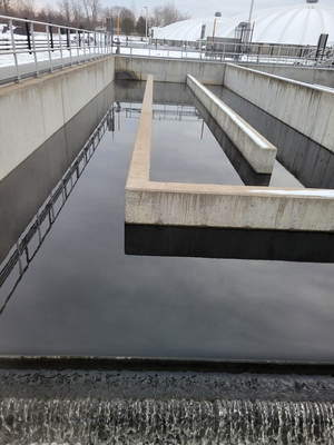
Final Clarifiers:
In addition to separating the floatable and settleable solids, the Final Clarifiers have an addition chemical process to remove phosphorous. Ferric Chloride (FeCl3) is used for the precipitation of the phosphorous. We have two final clarifiers, and they operate in a parallel to each other. In final settling tank "A" the settled sludge is removed from the tank by two final sludge pumps. For Final Settling Tank "B," the settled sludge is removed from the tank by means of a return sludge pump which recycles sludge back to the head of the aeration tanks. Excess or waste activated sludge (WAS) is removed from the Final "B" tank as needed and transferred to the sludge thickeners for processing in the sludge Disposal building.
Disinfection:
The Black River is considered a recreation river requiring disinfection of discharged water during the months of April through October. Sodium hypochlorite solution is used to reduce the fecal coliform count below the permit limit of 200mpn/100ml, Sodium bisulfite is used for de-chlorination to reduce the concentration of residual chlorine below the permit level of 0.8 mg/l. The chlorine contact tanks for both trains are sized for a minimum contact time of 15 minutes at peak flow.
Biosolids handling
Sludge treatment and disposal:
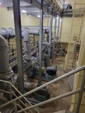
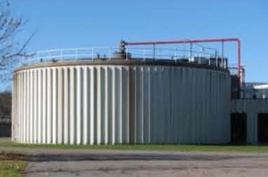
The sludge from the primary and secondary clarifiers is pumped to the gravity thickener at about 0.1% solids. The thickener utilizes the physical process of settling and gravitational compaction to thicken the sludge up to approximately 6% solids by weight. An approximate 1.5 days of sludge retention time is maintained.
Sludge Thickener Tanks
Longer retention times run the greater risk of sludge becoming septic. The sludge is pumped from the gravity thickener to the anaerobic digester.
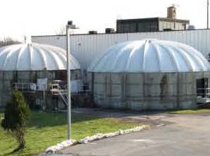
Anaerobic digesters:
 Primary Digester
 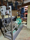 Digester mixing pump
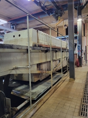
Biosolids Disposal
1. Chemical conditioning and dewatering
2. Land application.
 Class B Biosolids
Chemical conditioning and dewatering cycles are done in the sludge disposal building. Sludge is pumped from either or both the thickener and /or digester to the sludge conditioning column. Polymer is added at the conditioning column, and from there the conditioned sludge will enter the aging tanks to complete the mixing and chemical curing of the sludge. From there, the sludge will gravity feed to the batch tanks. The batch tanks serve as a reservoir from which the filter press feed pumps will draw sludge to feed the filter presses on the second floor. Chemical Conditioning The filter presses operate at 250 psi and will produce a sludge cake of approximately 30 % solids by weight. The sludge cake will then be conveyed via drag conveyors to a conveyor belt transporting biosolids to a truck to be stored on a until it is hauled away to local farm fields. The biosolids produced at the City of Watertown Pollution Control facility are rated as Class B meaning they are utilized for secondary human consumption. The Class B biosolids can be applied to farm fields for fertilizer to grow hay or corn for animal feeding.
Industrial Pretreatment program:
This program deals with Industrial users which are hard piped to our facility (examples are the NY Airbrake, Knowlton Technologies, seven ground water recovery units on Fort Drum, etc.) along with sludge haulers and septic haulers from outside the city. The facility currently has 48 different point sources outside the city that are permitted to haul sludge to the facility. Pretreatment is a method by which an industry can be brought into compliance with local waste discharge ordinances as well as Federal and State regulations. The types of waste originating from such point sources depend on the raw material used, production processes and the ability to recover and recycle waste on site. To ensure that industrial discharges meet acceptable standards, the pretreatment facility inspector must inspect each treatment process or facility at each point source, as well as routinely sample tanker deliveries at the City’s facility.
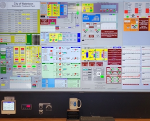
SCADA
Supervisory Control and Data Acquisition (SCADA) system that is currently being used at the facility was installed by the facility’s staff and is currently maintained by the plant staff. The SCADA offers the operator a quick snapshot of the facility along with automatic or semi-automatic control of pumps, gates, flow charts and chemical dosing. The system is also tied into the City’s remote lift stations. If there is a problem at one of the lift stations an alarm is signaled on the display panel alerting facility staff of impending issues. As the data is recorded in the SCADA, the data is automatically manipulated to trend plant performance, further enhancing process control.